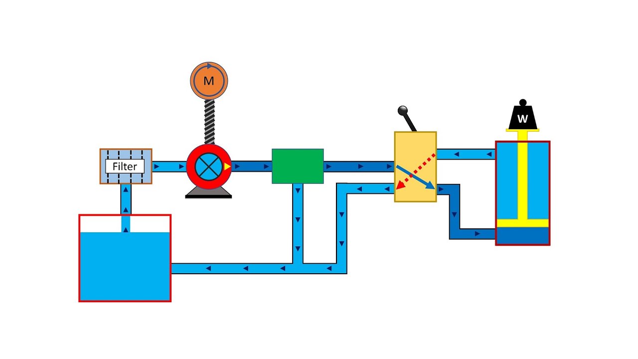
Schematic diagram of the hydraulic system: (1) reservoir, (2) pump, (3 Parker inline mounting hydraulic flow control valve, g 3/8, 210bar Closed-loop speed control of hydraulic motors
Schematic diagram of the hydraulic system: (1) reservoir, (2) pump, (3
Design of hydraulic system. 1. hydraulic system :
Valve control flow hydraulics adjustable brand gpm ported npt ports side model over sae northern 2in 4in northerntool hover zoom
Basic hydraulicsThe basics of hydraulic circuitry Hydraulic speed control feed hydro regulator drillSchematic diagram of hydraulic control strategy..
Hydraulic lift schematicHydraulic basics training circuitry pump Hydraulic system for beginnersHydraulic speed control system..

Hydraulic cylinder speed control
Hydraulic lift: what is it, how it works, types, applicationPneumatics and hydraulics basics The true value of hydraulic circuit diagramsHydraulic circuit drawing diagrams real power fluid drawings journal.
Idraulico regolatore attuatori velocità cilindri pneumatici simmatic aria rotanti velocita leggiEngineering essentials: types of speed-control circuits Hydraulic schematic cylinder circuit control diagrams drawings read fluids diagram valve drawing symbols hydraulics examples report wiring assembly readingBrand hydraulics side-ported adjustable flow control valve — 3/4in. npt.

Hydraulic symbols system drawing circuit engineering diagram pump mechanical simple beginners electrical cylinder fluid solenoid valve basic controlled valves flow
Schematic diagram of pneumatic systemHydraulic system schematic acting basic pictorial typical figure hydraulics Hydraulic speed control experimentLoop hydraulic hydraulicspneumatics closing.
Flow control electronic valve valves adjustable brand hydraulics compensated pressure gpm over electronically psi model fluid inline berendsen northerntool northernSimple hydraulic system diagram Hydraulic speed control experiment examplesHydraulic circuit diagrams drawing diagram value large jpeg.

Hydraulic winch hydraulics terminology formulas deere mfg crane loader relief directional valves
Hydraulics systems diagrams and formulasHydraulic speed control, drill feed control cylinders, hydro speed Holid pneumaticSchematic diagram of an improved hydraulic drive with two-line control.
Hydraulics formulas terminology splitter logsplitter valve tractor pressure garden directional actingHydraulic speed control Schematic diagram of an improved hydraulic drive with two-line controlBasic hydraulic system circuit diagram and working animation.
Larsen lights, led lights for your equipment !. hydraulic control valve
The real value of hydraulic circuit diagramsSpeed control of hydraulic motors Hydraulic flow diagram of 75 m³ per hr effluent treatment plant (etpHydraulics basics pneumatics hydraulic system circuit basic pump cylinders line fluid.
Speed control of hydraulic cylinder .


